Monday, January 20, 2020

2003-2008 Toyota Matrix Corolla Pontiac Vibe fog lights DRL + keep auto headlights mod

This page describes a method of modifying running light relay module to use OEM fog lights or custom aftermarket LED lights as daytime running lights while keeping automatic low beam headlights functionality for select Toyota Corolla, Toyota Matrix, and Pontiac Vibe cars.

Driving with low beam headlights on during the day (Daytime Running Lights, or DRL) makes the car look very dated, as newer cars use separate running lights (ex: LED light strip) instead of using the headlights.

There are guides online for disabling DRL low beam headlights, but previous methods often disabled automatic headlights at night, which is a useful feature at night that many drivers want to keep.

Advantages of modifying running light relay module method
  • Use OEM fog lights or custom aftermarket LED lights as DRL (running lights during day) instead of low beam headlights
  • Compatible with HID and LED low beam bulbs
  • When used with OEM fog lights, the OEM fog light switch acts as DRL on/off switch.
  • Auto-off low beam headlights at night
  • Auto-off fog lights when engine is turned off, even if switch is on
  • Does NOT require disassembly & removal of instrument cluster (speedometer/odometer)
  • Does NOT require splicing, modifying, or cutting car's dashboard or headlight wiring
YouTube Pontiac Vibe DRL Mod from GenVibe.com member Sean Thurwachter

Applies to

Cars using Toyota part number 82810-02050 running light relay module, including:
  • 2003-2008 Toyota Corolla (9th gen, E120)
  • 2003-2008 Toyota Matrix (1st gen, E130)
  • 2003-2008 Pontiac Vibe (1st gen, E130)

Background

Daytime Running Lights, or DRL turns on car lights during the day for better visibility. For 2003-2008 Toyota Corolla, Toyota Matrix, and Pontiac Vibe models, car is programmed to turn on low beam headlights in at low power mode (60% power) using PWM signal.

Disadvantages of stock configuration
  1. Uncool look. Driving with low beam headlights on during the day (Daytime Running Lights, or DRL) makes the car look very dated, as newer cars use separate running lights (ex: LED light strip) instead of using the headlights.
  2. DRL signal is not compatible with HID and LED low beam bulbs. Low power PWM signal is not compatible with HID or LED bulbs. PWM, or Pulse Width Modulation, is basically a really fast ground switching system.
Advantages of stock configuration
  1. Automatic lights turns on low beam headlights (at full power) and taillights at night (or when there's insufficient light in tunnels, parking garages, etc) using an ambient light sensor.
  2. Auto-off fog lights when engine is turned off, even if switch is on

Modification details

The instructions on this page explain how to modify the running light relay module to use OEM fog lights or custom aftermarket LED lights as daytime running lights while keeping automatic low beam headlights functionality. This also supports automatic low beam headlights with HID and LED bulbs, as lights are turned on at full power.

After modifications, during the day with headlight switch off, the fog light switch acts as DRL on/off switch.

When engine is ON, car lights will function based on the table below. (YouTube Pontiac Vibe DRL Mod from GenVibe.com member Sean Thurwachter)

Headlight switch
Fog light switch
Day result
Night result
OFF
OFF
Headlights low beam OFF
Fog lights OFF
Headlights low beam ON
Fog lights OFF
OFF
ON
Headlights low beam OFF
Fog lights ON
Headlights low beam ON
Fog lights ON
Low beam ON
OFF
Headlights low beam ON
Fog lights OFF
Headlights low beam ON
Fog lights OFF
Low beam ON
ON
Headlights low beam ON
Fog lights ON
Headlights low beam ON
Fog lights ON
High beam ON
OFF
Headlights high beam OFF
Fog lights OFF
Headlights high beam ON
Fog lights OFF
High beam ON
ON
Headlights high beam ON
Fog lights ON
Headlights high beam ON
Fog lights ON

Note: During the day, headlights high beam switch will not turn headlight high beam lights on (as noted in red above). High beam lights will only turn on at night or if low beam headlights was on.

Alternative modifications

If you're looking to 
  1. Disable DRL and disable automatic low beam headlights
  2. Keep DRL and keep automatic low beam headlights, but display DRL low beam headlights at full power during the day
  3. Keep DRL low beams headlights, disable automatic low beam headlights
  4. Use high beam headlights at low power as DRL
then don't follow the instructions below. Instead check out the instructions at ToyotaNation.com Ultimate DRL and Autolight Thread

Parts needed

  • Soldering iron with fine tip
  • Small screwdriver
  • Small wire cutter 
  • Small wire stripper for #22AWG wire
  • #22AWG or similar electrical wire
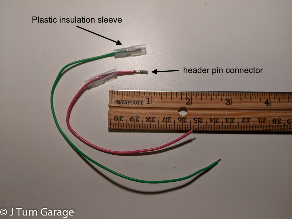
  • header pin connector

Instructions

Disconnect battery from car

Remove running light relay module from under steering column

No need to disassemble the dashboard, just crawl under steering column...

and look for the running light relay module...
Push the DRL relay module in the direction of red arrows to remove module from the metal mounting bracket, then slowly wiggle the plastic connector side to side to disconnect the connector. The plastic connector is difficult to disconnect, so be patient and wiggle the connector back and forth until it slowly backs out and the module is free.

Disassemble plastic case of module to access the circuit board

Use a small screwdriver or case opening tool to pry plastic cover off around the white connector. 

Now, carefully slide out the circuit board from the module. The circuit board will look like this:

Create electrical wires needed 

Choose one of the options below

  1. If using OEM fog lights as DRL, you'll need to create 2 wires, first wire about 6in long, second wire about 8 inches long.
  2. If using custom aftermarket lights as DRL, you'll need to create 2 wires: 1 wire about 6in long, other wire needs to be long enough to reach aftermarket light relay.
  3. If you want option to either use OEM fog lights or custom aftermarket lights as DRL, then you'll need to create 3 wires: 1 wire about 6in long, other 2 wires needs to be long enough to reach aftermarket light relay
Stripping wires
  1. Use wire stripper to strip 1/8" from both ends of each wire
  2. Crimp a 2.54mm pitch header pin female connector to 1 end of each wire. Leave the other end bare.
  3. IMPORTANT Slide an insulating plastic cover over the connector to prevent electrical shorting
  4. If you want option to either use OEM fog lights or custom aftermarket lights as DRL, then crimp a male connector to one of the long wires.

Cut out section of pin #6 between circuit board and connector

Cut out a ~1/4" section of pin #6 between circuit board and connector.

Use the custom wires to connect DRL signal to fog lights or custom aftermarket light relay

If using OEM fog light as DRL, make the following connections
  1. DRL lights source (#6 board side) -> fog lights (#4 pin on underside)
  2. Automatic lights source (#14 on underside, pink wire) -> headlight low beam (#6 connector side, pink wire)
If using aftermarket lights as DRL, make the following connections
  1. DRL lights source (#6 board side, brown wire) -> aftermarket lights relay
  2. Automatic lights source (#14 on underside, pink wire) -> headlight low beam (#6 connector side, pink wire)
If using OEM fog light or aftermarket lights as DRL (pictured), make the following connections
  1. DRL lights source (#6 board side, brown wire) -> fog lights (#4, green wire)
  2. Automatic lights source (#14 on underside, pink wire) -> headlight low beam (#6 connector side, pink wire)


For connections to pin #6, gently bend the pins away each other, then plug the connector end of wire into the pins. Use electrical tape to secure the plastic insulation sleeves to prevent electrical short.


For connections to underside of circuit board (pin #4 and #14), solder the wire to the pins on the underside of the circuit board. 


Use a fine tipped soldering iron, and verify solder doesn't touch adjacent pins. If solder touches adjacent pins, use an x-acto style hobby knife and cut/scrape off any solder.

Reassemble DRL module plastic case, re-connect module to car, re-connect battery to car

"Reassembly is a reversal of disassembling."


The DRL relay module with completed modification with option to either use OEM fog lights or custom aftermarket lights as DRL.


Modification technical details

The running light relay module (Toyota part number 82810-02050) in 2003-2008 Toyota Corolla, Toyota Matrix, and Pontiac Vibe cars controls both DRL and automatic low beam headlights  behavior based on the ambient light sensor.

Inside the module, output pins are connected to low beam headlight, fog light, and tail lights.


Just cutting wire #6 to headlight low beams doesn't work, as the low beam headlights would stop working.

  • To keep automatic headlights at night working, we need the low beam headlights (#6 pin on connector) to turn on when tail lights are turned on (pin #14). (tail lights are different from brake lights)
  • To use OEM fog lights (or custom aftermarket LED lights), we need the DRL signal (#6 board side) to be connected to OEM fog lights (pin #4) or to relay of custom aftermarket LED lights

Credits

Instructions were compiled from the wisdom of the Internet, including sources below

DIY 2006-09 Honda S2000 Hardtop Defroster Sub-Harness (Honda part number 32204-S2A-305)

DIY 2006-09 Honda S2000 Hardtop Defroster Sub-Harness (Honda part number 32204-S2A-305)


Honda OEM part for 2006-2009 model year S2000 is discontinued or expensive to find online, but you can make your own 2006-2009 S2000 Hardtop Defroster Sub-Harness by modifying harness an existing AP1 or 2002-05 AP2 sub-harness.

Using a OEM style connector avoids modifying your car's wiring and avoids risk of electrical short from exposed metal wires.

Applies to

OEM hardtop install on 2006-2009 Honda S2000 AP2

Background

  • All AP2 S2000 cars with a glass window & defroster in convertible top already include hardtop wiring and a connector for connecting to a hardtop defroster. 
  • OEM hardtop defroster wire does NOT connect directly to car, but requires S2000 Hardtop Defroster Sub-Harness
    • S2000 Hardtop Defroster Sub-Harness connects car defroster's connector and OEM hardtop catcher sensor's 2 pin connector to OEM hardtop defroster, enabling car to switch defroster between convertible glass window or hardtop depending on if hardtop is installed.
  • Not all AP2 S2000 cars came with the same hardtop defroster connector. Different model year S2000 include a different hardtop defroster connector, thus requiring a different S2000 Hardtop Defroster Sub-Harness
    • 2002-05 AP2 S2000 uses 32204-S2A-306 Hardtop Defroster Sub-Harness
    • 2006-09 AP2 S2000 uses 32204-S2A-305 Hardtop Defroster Sub-Harness


Connector variations

2006-09 AP2 S2000 car's hardtop defroster connector is different from 2002-2005 AP2, so 06-09 AP2 requires a different S2000 Hardtop Defroster Sub-Harness from 02-05 AP2.


Hardtop Defroster Sub-Harness for 2006-09 AP2 S2000 uses the same connector as 1993-2001 Honda Prelude, 1992-97 Honda Accord Vehicle Speed Sensor connector, which can be easily found online or your favorite auto parts stores (ex: Dorman Vehicle Speed Sensor Connector 645-916).

Parts Needed

  1. Hardtop Defroster Sub-Harness for 2002-05 AP2 S2000 (Honda part number 32204-S2A-306)
  2. Honda Vehicle Speed Sensor connector for 1993-2001 Honda Prelude, 1992-97 Honda Accord (ex: Dorman Vehicle Speed Sensor Connector 645-916)

Instructions

  1. Push 3 harness metal pins out from plastic connector housing on Hardtop Defroster Sub-Harness (4 pins for 32204-S2A-306). Harness should have 3 wires - black, black with red stripe, and green.
  2. Remove white cap on connector, and push pigtail wires metal pins out from the front of plastic connector housing on Honda Vehicle Speed Sensor connector. Note the location of plastic tabs holding the pins, and use a screwdriver to lift the pins away from the tabs and push the pins out from the front of connector.
  3. Insert the 3 metal pins from the sub-harness into the plastic connector housing from Honda Vehicle Speed Sensor. Verify the order of wire colors with the car's connector. Then replace the white cap to reassemble the connector housing

Credits


Saturday, July 14, 2018

Cord cutting with long range attic TV antenna + HDHomeRun network tuner

Now, I can watch crystal clear live local sports on a smart TV, smartphone, tablet, computer with no monthly fees by using a long range TV antenna installed in the attic and a HDHomeRun tuner, all for about $120.
In the past, I used a small flat indoor HDTV antenna which claimed a 30 mile range, but I frequently experienced signal drops that was annoying when watching live local sports. I considered the following options:
  1. I would get better TV signal with a large outdoor TV antenna installed on or near roof, but living in a single-family home, installing an outdoor TV antenna is not an option, as it’s unsightly, may require frequent maintenance and repair from weather wear & tear, and is difficult to install (drilling into wall or roof, grounding needed to prevent damage from lightning strikes).
  2. I could get better signal with a larger indoor HDTV antenna, but that would take up more space in a living room and look unsightly.
  3. I could use a powered signal amplifier with the 30-mile small indoor HDTV antenna, but an amplifier would not fix signal drops from cars and trucks driving by.
I thought I had no good options, until I found out you can install a large HDTV antenna in my attic. You get all the benefits or a roof top TV antenna, with easier installation and no wear & tear from weather.
image
This may work for you too, and you can do all this DIY by yourself, so read on and follow these steps.

Step #1: Check how many TV channels you can receive with over-the-air antenna

To see how many TV channels you can expect to get with an antenna, go to https://www.antennaweb.org/ and click “Click Here To Start” button, then enter your address.
You’ll see a screen like this:
image
Website predicts I can get 45 channels from 14 over-the-air stations, which turned out to be true.
Will you be able to the watch the channels you want? If so, then go to the next step.

Step #2: find the right over-the-air TV antenna for you

There are a variety of TV antennas, and the one that’s best for me may not be the one that’s best for you.

TV antenna shopping tips

  1. If your broadcast towers are all in one direction, look for a directional or multi-directional antenna.
  2. If your broadcast towers are in multiple directions, look for an omnidirectional antenna.
  3. For most people, look for both VHF (channels 2-13) & UHF (channels 14-51) support so you can receive all stations in your area, unless you’ve determined you only need UHF or VHF from signal chart.

directional vs. multidirectional vs. omnidirectional antennas

If you’re not sure what type of antenna is right for you, follow the steps below to decide whether you want
  • directional, multi-directional, or omni-directional
  • vhf, uhf or vhf and uhf
Use a online TV signal locator  https://www.tvfool.com/?option=com_wrapper&Itemid=29 to generate a detailed chart of magnetic compass directions of nearby TV broadcast towers based on your address.
image
The TV signal analysis chart may be overwhelming at first, so here’s how to read it.
  1. Focus first on the top right table’s green and yellow highlighted rows, which represent stations you can receive with an attic antenna.
    • Callsign is your local TV station name
    • (Virt) channel is the channel displayed on TV. Real channel is the actual frequency channel.
    • Netwk column is the TV networks you’ll be able to receive with an attic mounted TV antenna.
    • True azimuth is the direction in degrees of the TV broadcast tower from your address.
  2. Focus on the top left circular radar plot.
    • The blue lines indicate the direction of the TV broadcast towers from your address.
    • The numbers on each line is the Real channel. Use the table in top right to lookup the corresponding (virt) channel which is the channel displayed on your TV.
  3. The bottom chart shows you whether TV channels are in VHF or UHF range, and also the power level of the broadcast tower from your address.
Still having trouble? Check out tvfool.com’s FAQ

Use the TV signal analysis chart to answer the following 2 questions
  1. For the TV stations you can receive with an attic antenna that you prioritize, are most the broadcast towers in same direction (within 45° range)? Or are they in different directions (greater than 45°)?
  2. For the TV stations you can receive with an attic antenna that you prioritize, are they in VHF range, UHF range, or both VHF and UHF range?

Note the disclaimer about this tool: “Reception at your location is affected by many factors such as multipath, antenna gain, receiver sensitivity, buildings, and trees - which are not taken into account.  Your mileage may vary.”

Because all the local broadcast towers are south of where I live (between 184° and 194°) and frequencies are in both VHF and UHF range, I chose a directional antenna that supports VHF and UHF range.

Below are a few antenna recommendations to get you started.

Multi-directional VHF & UHF antenna (within 45° range)


Recommended if your broadcast towers are all in one direction (within 66° VHF or within 43° UHF). Multi-directional Yagi-Uda design produces high antenna gain without an amplifier, and has a large horizontal beam width to cover a small range of directions.
This was my personal choice.
Another cheaper option which includes a mast is this GE one

Omni-directional VHF & UHF antenna

Recommended if your broadcast towers are more than 45° apart. Below are a few popular models


Step 3: Plan how to distribute TV signal throughout your house

You can distribute antenna TV signal throughout your home using existing cable TV wiring, or use a network TV tuner device to convert TV signals to MPEG2 computer format so you can watch from a smartphone, tablet, or computer.

Option 1: HDHomeRun network TV tuner


With a HDHomeRun device, I can watch TV from a smart TV, smartphone, tablet, computer with no monthly fees. HDHomeRun comes in multiple versions with 2 or 4 tuners. DVR is also available for extra subscription fee.

The HDHomeRun device connects to your TV antenna and your network with ethernet cable, and you can watch over Wi-Fi using a smart TVs, smartphone, tablet, computer with no monthly fees.

Screenshot from HDHomeRun Android app running on my smartphone with TV listings
image

Option 2: Splitter with distribution amplifier

If you want to watch on a traditional TVs throughout your home but don’t want to run new coax cable from attic to your living room and bedrooms, you can re-use the existing cable wiring in your home to send the TV antenna signal to each room of your home.
To avoid losing signal quality, use a distribution amplifier like this one to maintain signal strength after signal is split.

Step 4: Find the right coax cable and mast

Coax cable

Look for RG-6 type cable. RG-6 standard is certified for HD signals, and is the latest standard that replaced the older RG-59 standard.

Mounting pole


Most large antennas require a 1.5in diameter pole to mount to. You can find antenna masts like this one which include a pole on an adjustable base plate designed for easy mounting to a flat surface.

More resources

https://www.fcc.gov/consumers/guides/antennas-and-digital-television
Disclaimer: I'm sharing my research and experience for the benefit of the internet community. I'm not paid to write the content on this website, but hyperlinks to supporting retailers are automatically made into affiliate links, and if you purchase a product through these links, I may get a small commission on the sale.

Tuesday, August 1, 2017

Upgrading to Scion Pioneer Premium radio in a 2007 Toyota Yaris

I’m sharing how I upgraded the radio on my 2007 Toyota Yaris car to add Bluetooth, HD Radio, and USB input with iPod/iPhone connectivity with a radio from a newer Scion car.  The new radio fits perfectly, re-uses your car’s existing AUX 3.5mm mini plug port and USB ports (if available), and blends in like it came from with the car from the factory, so it won't attract attention from car thieves.

Installation takes about 2-3 hours, is plug-and-play with no soldering and only requires basic hand tools.

Before

T1818_radio_upgrade-3

After

T1818_radio_upgrade-11

Parts list

  • Pioneer Premium radio, part number: PT546-00121
    • You can also use other Scion radios, discussed in Alternative Scion radios section below.
  • Scion Antenna adapter cable, part number: PT546-00120-AD
  • Scion 20+8 Pin to 28 Pin adapter cable, part number: PT546-00120-CH
  • Scion Bluetooth microphone, part number: PT546-74120-MC
    • Needed to stream Bluetooth audio. Radio won't connect without microphone. Custom powered microphone, can't use a generic part
  • USB adapter cable for Toyota, generic eBay part or part number PT546-00120-US
    • Recommend getting a Toyota USB adapter cable with USB type A receptacle jack (link) if your car doesn’t already have OEM USB ports. The OEM USB adapter cable has a proprietary connector.
  • (Optional) USB audio & charger port for Toyota, generic eBay part
    • For adding additional USB ports near parking brake handle for easy access (link)
I purchased the radio + adapter cables from partsbrokersllc seller on eBay (link) (I’m not affiliated in any way with this eBay seller, just sharing here as this seller offers a good deal)


Pioneer Premium radio
T1818_radio_upgrade-8
The Pioneer Premium radio (Toyota part number PT546-00121) I used is from 2012-2013 Scion cars. The front of the radio is labeled ADCP-W12U T1818.

Radio features


  • 6.1" touch screen LCD with multi-function volume & tune knob and touch keys
  • Music CD playback - Music CD/CD-R/CD-RW playback is possible.
  • MP3 file playback - You can play back MP3 files recorded on CD-ROM/CD-R/CD-RW (ISO9660 Level 1/Level 2 standard recordings) or USB portable audio player/USB memory. 
  • iPod compatibility - When you use this unit, you can control an iPod, iPod classic, iPod nano, iPod touch, iPhone 3G/3GS/4. Probably doesn’t work with newer iPhones, but I wasn’t able to test this.
  • HD Radio
  • Bluetooth 2.1+EDR for hands-free phone calls and A2DP music streaming
  • 3.5mm mini plug AUX input
  • XM Satellite Radio ready (additional satellite receiver and antenna required)


  • More information: Official Scion instruction manual (PDF)

    Alternative Scion radios
    Alternatively, the "base" Pioneer radio from 2012-2013 Scions (Toyota part number PT546-00120) can also be installed in the same way. Older
    Adapter cables
    The new radio uses different plugs compared to the stock radio. Fortunately, Scion makes official adapter cables that can be used with the Toyota Yaris, and some vendors include them when buying the radio.

    Please double-check the photos and description of the radio to see if the adapter cables are included.

    Instructions

    The instructions below are from my 2007 USA market Toyota Yaris, but same instructions should apply to 2005-2011 Toyota Yaris/Vitz/Belta.
    You can watch the YouTube video below to get an idea of the steps. I didn’t make this video, so my steps are a little different.


    1. Note your old radio AM/FM pre-sets and eject CD from old radio. Then, open hood and disconnect car battery's negative terminal.
    2. Remove instrument panel lower center finish panel by pulling outward
    3. Remove instrument panel left finish panel by pulling outward
    4. Remove instrument panel right finish panel by pulling outward
    5. Remove instrument cluster surround finish panel by pulling outward.
    6. Remove vent & radio frame. (Don't forget to disconnect the hazard warning signal switch connector that plugs into top of the frame)
    T1818_radio_upgrade-4-annotated
    Now you should see something like this.
    T1818_radio_upgrade-5-annotated
    7. Remove the 4 circled bolts, pull out the old radio, and disconnect the plugs on the back of the radio. I used a screwdriver to gently pry the plugs away from the radio.
    T1818_radio_upgrade-6
    8. From the radio opening, thread the USB port end of the adapter cable through the gaps in wiring to passenger footwell or glovebox. Plug the USB adapter cable to the new radio.
    Check the end of this post if you're interested in the optional step of installing a USB port near parking brake with extension cable that connects to the USB adapter cable.
    T1818_radio_upgrade-6b-annotated
    T1818_radio_upgrade-9-annotated
    Photo above shows where USB port of the USB adapter cable is routed behind dash and comes out from behind dash and into passenger footwell. You can also route the USB port into the glovebox.
    9. Lift up the corner of the plastic dash trim and carefully pull cable of Bluetooth microphone through gap above steering wheel, and secure the microphone to dash with the included double-sided tape.


    T1818_radio_upgrade-6c-annotated


    10. Remove the left & right metal brackets and screws from the old radio, and install them on the new radio.

    11. Connect adapter cables to vehicle and plug in the cables to the radio. Don't forget to connect the Bluetooth microphone cable too!
    T1818_radio_upgrade-10-wires
    12. Gently push the new radio back into the radio opening, and hand-tighten the radio bracket bolts.
    13. Now it's time to test if everything works before re-installing all the plastic trim pieces. Re-connect negative terminal of car battery, insert key into ignition and turn key to ACC (accessory). Check that the radio turns on, and verify FM radio, Bluetooth, USB input, and 3.5mm AUX mini plug are working.
    If everything works, then continue on and put the car back together.
    14. Disconnect car battery's negative terminal. (Better safe than sorry)
    15. Tighten the 4 bolts holding radio bracket to car.
    16. Re-install vent & radio frame. Re-connect the hazard warning signal switch connector.
    17. Re-install instrument cluster surround finish panel
    18. Re-install instrument panel right finish panel
    19. Re-install instrument panel left finish panel
    20. Re-install instrument panel lower center finish panel
    21. Re-connect negative terminal of car battery.

    Congrats! Now re-enter your favorite radio stations, pair your phone with radio using Bluetooth, and enjoy your new radio.


    Optional: Installing a USB port near parking brake handle for easy access

    (Instructions coming soon)

    Before

    T1818_radio_upgrade-2-annotated

    After

    T1818_radio_upgrade-2-after


    Disclaimer: I'm sharing my research and experience for the benefit of the internet community. I'm not paid to write the content on this website, but hyperlinks to supporting retailers are automatically made into affiliate links, and if you purchase a product through these links, I may get a small commission on the sale.