Driving with low beam headlights on during the day (Daytime Running Lights, or DRL) makes the car look very dated, as newer cars use separate running lights (ex: LED light strip) instead of using the headlights.
There are guides online for disabling DRL low beam headlights, but previous methods often disabled automatic headlights at night, which is a useful feature at night that many drivers want to keep.
Advantages of modifying running light relay module method
- Use OEM fog lights or custom aftermarket LED lights as DRL (running lights during day) instead of low beam headlights
- Compatible with HID and LED low beam bulbs
- When used with OEM fog lights, the OEM fog light switch acts as DRL on/off switch.
- Auto-off low beam headlights at night
- Auto-off fog lights when engine is turned off, even if switch is on
- Does NOT require disassembly & removal of instrument cluster (speedometer/odometer)
- Does NOT require splicing, modifying, or cutting car's dashboard or headlight wiring
Applies to
Cars using Toyota part number 82810-02050 running light relay module, including:
Background
Daytime Running Lights, or DRL turns on car lights during the day for better visibility. For 2003-2008 Toyota Corolla, Toyota Matrix, and Pontiac Vibe models, car is programmed to turn on low beam headlights in at low power mode (60% power) using PWM signal.
Disadvantages of stock configuration
- Uncool look. Driving with low beam headlights on during the day (Daytime Running Lights, or DRL) makes the car look very dated, as newer cars use separate running lights (ex: LED light strip) instead of using the headlights.
- DRL signal is not compatible with HID and LED low beam bulbs. Low power PWM signal is not compatible with HID or LED bulbs. PWM, or Pulse Width Modulation, is basically a really fast ground switching system.
Advantages of stock configuration
- Automatic lights turns on low beam headlights (at full power) and taillights at night (or when there's insufficient light in tunnels, parking garages, etc) using an ambient light sensor.
- Auto-off fog lights when engine is turned off, even if switch is on
Modification details
The instructions on this page explain how to modify the running light relay module to use OEM fog lights or custom aftermarket LED lights as daytime running lights while keeping automatic low beam headlights functionality. This also supports automatic low beam headlights with HID and LED bulbs, as lights are turned on at full power.
After modifications, during the day with headlight switch off, the fog light switch acts as DRL on/off switch.
When engine is ON, car lights will function based on the table below. (YouTube Pontiac Vibe DRL Mod from GenVibe.com member Sean Thurwachter)
Note: During the day, headlights high beam switch will not turn headlight high beam lights on (as noted in red above). High beam lights will only turn on at night or if low beam headlights was on.
After modifications, during the day with headlight switch off, the fog light switch acts as DRL on/off switch.
When engine is ON, car lights will function based on the table below. (YouTube Pontiac Vibe DRL Mod from GenVibe.com member Sean Thurwachter)
Headlight switch
|
Fog light switch
|
Day result
|
Night result
|
OFF
|
OFF
|
Headlights low
beam OFF
Fog lights OFF
|
Headlights low
beam ON
Fog lights OFF
|
OFF
|
ON
|
Headlights low
beam OFF
Fog lights ON
|
Headlights low
beam ON
Fog lights ON
|
Low beam ON
|
OFF
|
Headlights low
beam ON
Fog lights OFF
|
Headlights low
beam ON
Fog lights OFF
|
Low beam ON
|
ON
|
Headlights low
beam ON
Fog lights ON
|
Headlights low
beam ON
Fog lights ON
|
High beam ON
|
OFF
|
Headlights high
beam OFF
Fog lights OFF
|
Headlights high
beam ON
Fog lights OFF
|
High beam ON
|
ON
|
Headlights high
beam ON
Fog lights ON
|
Headlights high
beam ON
Fog lights ON
|
Note: During the day, headlights high beam switch will not turn headlight high beam lights on (as noted in red above). High beam lights will only turn on at night or if low beam headlights was on.
Alternative modifications
If you're looking to
- Disable DRL and disable automatic low beam headlights
- Keep DRL and keep automatic low beam headlights, but display DRL low beam headlights at full power during the day
- Keep DRL low beams headlights, disable automatic low beam headlights
- Use high beam headlights at low power as DRL
then don't follow the instructions below. Instead check out the instructions at ToyotaNation.com Ultimate DRL and Autolight Thread
Parts needed
- Soldering iron with fine tip
- Small screwdriver
- Small wire cutter
- Small wire stripper for #22AWG wire
- #22AWG or similar electrical wire
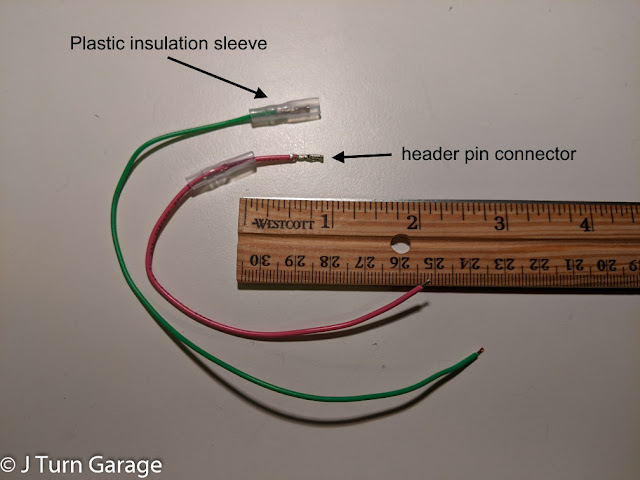
- header pin connector
Instructions
Disconnect battery from car
Remove running light relay module from under steering column
No need to disassemble the dashboard, just crawl under steering column...
and look for the running light relay module...
Push the DRL relay module in the direction of red arrows to remove module from the metal mounting bracket, then slowly wiggle the plastic connector side to side to disconnect the connector. The plastic connector is difficult to disconnect, so be patient and wiggle the connector back and forth until it slowly backs out and the module is free.
Disassemble plastic case of module to access the circuit board
Use a small screwdriver or case opening tool to pry plastic cover off around the white connector.
Now, carefully slide out the circuit board from the module. The circuit board will look like this:
Create electrical wires needed
Choose one of the options below
- If using OEM fog lights as DRL, you'll need to create 2 wires, first wire about 6in long, second wire about 8 inches long.
- If using custom aftermarket lights as DRL, you'll need to create 2 wires: 1 wire about 6in long, other wire needs to be long enough to reach aftermarket light relay.
- If you want option to either use OEM fog lights or custom aftermarket lights as DRL, then you'll need to create 3 wires: 1 wire about 6in long, other 2 wires needs to be long enough to reach aftermarket light relay
Stripping wires
- Use wire stripper to strip 1/8" from both ends of each wire
- Crimp a 2.54mm pitch header pin female connector to 1 end of each wire. Leave the other end bare.
- IMPORTANT Slide an insulating plastic cover over the connector to prevent electrical shorting
- If you want option to either use OEM fog lights or custom aftermarket lights as DRL, then crimp a male connector to one of the long wires.
Cut out section of pin #6 between circuit board and connector
Cut out a ~1/4" section of pin #6 between circuit board and connector.
Use the custom wires to connect DRL signal to fog lights or custom aftermarket light relay
If using OEM fog light as DRL, make the following connections
- DRL lights source (#6 board side) -> fog lights (#4 pin on underside)
- Automatic lights source (#14 on underside, pink wire) -> headlight low beam (#6 connector side, pink wire)
If using aftermarket lights as DRL, make the following connections
- DRL lights source (#6 board side, brown wire) -> aftermarket lights relay
- Automatic lights source (#14 on underside, pink wire) -> headlight low beam (#6 connector side, pink wire)
If using OEM fog light or aftermarket lights as DRL (pictured), make the following connections
- DRL lights source (#6 board side, brown wire) -> fog lights (#4, green wire)
- Automatic lights source (#14 on underside, pink wire) -> headlight low beam (#6 connector side, pink wire)
For connections to pin #6, gently bend the pins away each other, then plug the connector end of wire into the pins. Use electrical tape to secure the plastic insulation sleeves to prevent electrical short.
For connections to underside of circuit board (pin #4 and #14), solder the wire to the pins on the underside of the circuit board.
Use a fine tipped soldering iron, and verify solder doesn't touch adjacent pins. If solder touches adjacent pins, use an x-acto style hobby knife and cut/scrape off any solder.
Reassemble DRL module plastic case, re-connect module to car, re-connect battery to car
"Reassembly is a reversal of disassembling."
The DRL relay module with completed modification with option to either use OEM fog lights or custom aftermarket lights as DRL.
Modification technical details
The running light relay module (Toyota part number 82810-02050) in 2003-2008 Toyota Corolla, Toyota Matrix, and Pontiac Vibe cars controls both DRL and automatic low beam headlights behavior based on the ambient light sensor.
Inside the module, output pins are connected to low beam headlight, fog light, and tail lights.
Just cutting wire #6 to headlight low beams doesn't work, as the low beam headlights would stop working.
- To keep automatic headlights at night working, we need the low beam headlights (#6 pin on connector) to turn on when tail lights are turned on (pin #14). (tail lights are different from brake lights)
- To use OEM fog lights (or custom aftermarket LED lights), we need the DRL signal (#6 board side) to be connected to OEM fog lights (pin #4) or to relay of custom aftermarket LED lights
Credits
Instructions were compiled from the wisdom of the Internet, including sources below


